
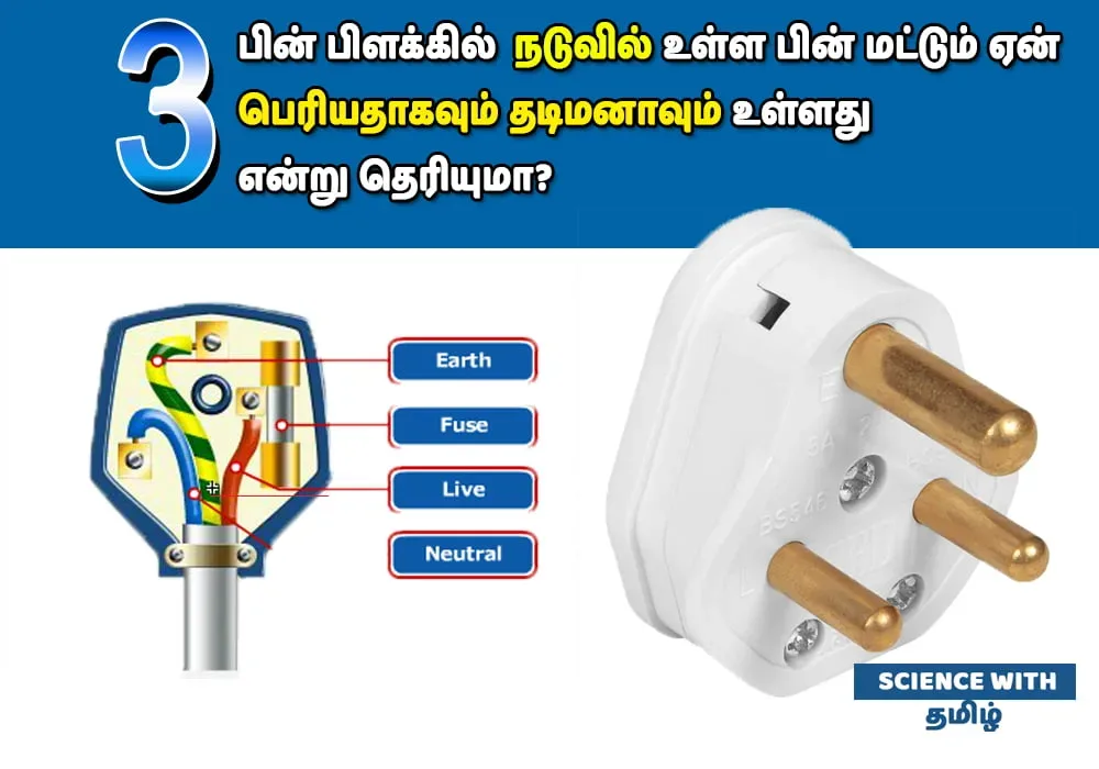


Every time you plug in a heavy domestic appliance–whether it is an electric iron, an air conditioner, a refrigerator, an immersion water heater, or a washing machine–you instinctively interact with a familiar three-pronged brass plug. If you look closely at the plug’s geometry, you will notice an unmistakable asymmetry: the top pin, designated as the Ground or Earth Pin, is visibly longer and distinctly thicker than the two parallel Live and Neutral pins beneath it [1].
Most people assume this dimensional mismatch is an arbitrary aesthetic convention or a random manufacturing artifact. In reality, that modest brass protrusion represents one of the most brilliant, life-saving innovations in the history of electrical power engineering. Every millimeter of its additional length and every fraction of a square millimeter added to its cross-sectional diameter is dictated by rigorous laws of electromagnetic physics and electrical safety standards [1], [2].
In modern domestic alternating-current (AC) electrical systems, standard wall outlets deliver voltages between 220 and 240 volts at 50 Hertz–a potential difference more than sufficient to deliver a lethal ventricular fibrillation shock to the human heart in less than one-tenth of a second. How does the asymmetric geometry of the earth pin safeguard human life without requiring active electronics or digital chips? The answer lies in the elegant physics of electrical resistance, mechanical sequencing, and fault current diversion [1], [2].
- < 0.1 Ω
- Earth Pin Resistance
- 1,000+ Ω
- Human Resistance
- 1st to Make
- Safety Sequence
- Last to Break
- Disconnect Rule
The Physics of Electrical Resistance: Pouillet’s Law and the Thicker Pin
To understand why the earth pin is made significantly thicker than the live and neutral pins, one must revisit a fundamental principle of classical electromagnetism known as Pouillet’s Law. Formulated by French physicist Claude Pouillet in 1838, this law establishes that the electrical resistance (R) of any uniform conductor is directly proportional to its length (L) and inversely proportional to its cross-sectional area (A), expressed by the formula: R = rho * (L / A), where rho represents the specific electrical resistivity of the material [1], [3].
In electrical engineering, current does not travel exclusively along a single pathway; when presented with multiple parallel conductive paths, electric current divides in inverse proportion to each path’s resistance (Ohm’s Law: I = V / R). If a high-voltage live wire inside a washing machine or electric iron breaks loose and touches the metal outer chassis, that metal casing immediately becomes energized at 230 volts. If an unsuspecting human touches that energized chassis while standing barefoot on a moist floor, two parallel conductive paths to ground are instantly formed: 1. The human body, which exhibits an electrical resistance ranging between 1,000 ohms (for moist skin) and 100,000 ohms (for dry skin). 2. The earth pin and grounding wire, which are directly bonded to the metal chassis [1], [3].
By intentionally increasing the cross-sectional area (thickness) of the brass earth pin, electrical engineers drastically minimize its internal resistance to less than 0.05 ohms. Because the grounding conductor’s resistance is thousands of times lower than the electrical resistance of the human body, the overwhelming majority (over 99.99%) of the dangerous fault current rushes harmlessly down the thick earth pin into the subterranean grounding pit, completely bypassing the human heart [1], [2].
Beyond minimizing resistance during everyday static dissipation, the earth pin’s substantial thickness is engineered to withstand catastrophic surge currents. When a severe short circuit occurs–such as a complete phase-to-chassis fault–the instantaneous current surge can exceed several hundred or even thousands of amperes before the Miniature Circuit Breaker (MCB) or fuse trips. A thin, delicate brass pin would instantly heat up, melt, or suffer thermal spot-welding under such intense Joule heating (P = I^2 * R). The thick brass core provides high thermal mass and current-carrying capacity, maintaining structural and electrical integrity until the circuit breaker disconnects the supply [2], [3]. Furthermore, in high-frequency transient fault events–such as lightning strikes propagating down domestic overhead transmission lines–the alternating surge current experiences skin effect, where current density crowds toward the outer surface of conductors. A thicker pin geometry provides substantially greater peripheral surface area, facilitating rapid inductive high-frequency surge dissipation without dielectric breakdown.
Mechanical Sequencing: The Life-Saving Logic of ‘First to Make, Last to Break’
While thickness governs electrical resistance and thermal resilience, the pin’s extra length solves a critical mechanical timing challenge known in electrical safety engineering as ‘First to Make, Last to Break’ [1], [2].
Consider what occurs in the microsecond timeline when a user pushes a three-pin plug into an energized wall socket. Because the top earth pin is physically longer by approximately 3 to 5 millimeters compared to the live and neutral pins, it makes physical and electrical contact with the internal socket terminal first. The metal appliance chassis is bonded to earth ground milliseconds before the live pin enters its phase socket [2].
This pre-emptive connection is crucial for human safety. If the appliance has suffered internal damage during storage–such as a frayed heating element touching the metal casing of an electric toaster or iron–the casing is already safely grounded before live current enters the appliance. If the switch happens to be turned on when the plug is inserted, the massive fault current immediately flows to ground and trips the residual current device (RCD) or circuit breaker instantly, preventing an innocent user from receiving an electric shock upon plug insertion [1], [2].
Conversely, when a user withdraws the plug from the wall socket, the reverse sequence occurs: the shorter Live and Neutral pins disconnect first, extinguishing the main electrical power supply while the longer Earth Pin remains firmly engaged. Ground protection is maintained until the very last fraction of a second when the plug completely exits the socket. Ground protection is never interrupted while high-voltage current is present [1], [3].
Operating the Gatekeeper: Safety Shutters in Modern Wall Sockets
In modern domestic and commercial electrical installations governed by international standards (such as British Standard BS 1363, Indian Standard IS 1293, and IEC 60884), wall sockets feature internal mechanical safety shutters designed to prevent accidental electrocution, particularly among curious children [2].
If you inspect a modern switched wall outlet, you will observe that the lower Live and Neutral apertures are physically blocked by spring-loaded plastic shutter doors. You cannot push a metallic screwdriver, nail, or a child’s finger into the live hole because the barrier is held shut by a rigid mechanical latch. How are these shutters opened when a legitimate plug is inserted? The longer earth pin acts as the mechanical key [2].
When a three-pin plug approaches the socket, the longer top pin enters the larger ground aperture first. As the earth pin penetrates inward, it presses down against an angled mechanical cam or linkage mechanism. This physical displacement lifts or swings open the lower shutter doors, clearing the path for the shorter Live and Neutral pins to enter smoothly [1], [2]. Without the leading penetration of the longer earth pin, the live terminal gates remain firmly locked.
This shutter-actuation mechanism prevents catastrophic household accidents. It ensures that dangerous live contacts cannot be exposed unless a proper, grounded plug is utilized. In certain high-safety configurations, the shutter mechanism will not unlock unless the top pin exerts sufficient physical pressure, making it virtually impossible for children to bypass the safety barrier with household objects. Tragically, many homeowners attempt dangerous improvisations, such as using ballpoint pens, wooden sticks, or metallic keys to force open the top shutter hole in order to insert a two-pin plug into a three-pin socket. Bypassing the shutter in this manner damages the internal spring mechanisms and risks direct contact with internal energized terminal busbars, creating an imminent flashover danger.
Anti-Inversion and Polarization: Preventing Catastrophic Phase Reversal
In alternating current (AC) electrical distribution, polarity and phase alignment are vital for user safety. While an AC load (such as a motor or heating resistor) will operate regardless of whether alternating current enters through the left or right terminal, appliance safety switches and internal fuses are strictly installed along the Live (Phase) line [1], [4].
If an appliance’s power supply lines were reversed–connecting the neutral line to the internal power switch while keeping the live wire connected directly to the internal chassis or heating coil–the appliance would remain energized with full 230-volt lethal potential even when turned ‘OFF’ at the front panel. Anyone opening the appliance for cleaning or maintenance would face severe shock hazards.
The asymmetric, triangular arrangement and the distinct thickness of the earth pin provide foolproof mechanical polarization. Because the earth pin is substantially larger in diameter and placed at the apex of an equilateral or isosceles triangle, it is physically impossible to insert a three-pin plug upside down or sideways into a standard socket. The plug can enter in exactly one orientation, guaranteeing that the Live pin enters the Live terminal and the Neutral pin connects to Neutral [1], [4]. Engineering precision and physical layout discipline are fundamental across electrical systems, mirroring principles seen in electromechanical control systems and engineering precision.
Class I vs Class II Appliances: Why Some Devices Have Only Two Pins
A frequent question among observant consumers is why heavy appliances feature thick three-pin plugs, whereas smartphones, laptops, television sets, table lamps, and electric shavers utilize lightweight two-pin plugs without an earth pin.
In electrical safety standards, appliances are rigorously classified based on their protective insulation architecture: 1. Class I Appliances (Basic Insulation + Protective Earthing): These appliances feature conductive metal outer frames or casings (e.g., washing machines, refrigerators, microwave ovens, water geysers, desktop computers). If the internal primary wire insulation chafes or degrades, electric current can energize the metal exterior. Therefore, mandatory grounding via a dedicated three-pin plug is legally required [1], [3]. 2. Class II Appliances (Double Insulated or Reinforced Insulation): These devices are engineered so that no single mechanical or electrical failure can expose hazardous voltage to the user. They feature non-conductive plastic outer casings or two completely independent layers of insulating barriers separating live wires from any external surface. Class II devices carry the official international safety symbol: two concentric squares (a square inside a square). Because there is zero risk of an exposed metal chassis carrying live current, an earth connection is superfluous, allowing the use of compact two-pin plugs [1], [4].
Plugging a Class I metal appliance into a socket using an altered, broken, or bypass two-pin adapter is an acute life-threatening hazard. If an internal insulation fault occurs, the ungrounded metal chassis remains live, waiting for a human touch to provide the path to ground through the user’s vital organs. Cutting off or physically bending the brass earth pin to force a three-pin plug into an old two-pin wall outlet is one of the leading causes of fatal domestic electrical accidents globally. Once the ground path is severed, the appliance loses its only fail-safe defense, turning everyday chores into potential electrocution traps.
Comparative Dimensional and Functional Analysis of Plug Pins
Evaluating the dimensional, electrical, and mechanical parameters of each pin in a standard heavy-duty plug highlights the deliberate engineering behind electrical safety.
| Design Parameter | Earth Pin (Top Apex) | Live Pin (Bottom Right) | Neutral Pin (Bottom Left) |
|---|---|---|---|
| Physical Length | Longer (~28.6 mm) | Shorter (~20.6 mm) | Shorter (~20.6 mm) |
| Pin Diameter / Thickness | Thicker (~8.7 mm diameter) | Thinner (~7.0 mm diameter) | Thinner (~7.0 mm diameter) |
| Electrical Resistance | Ultra-low (< 0.05 Ω) for rapid fault diversion | Standard load carrying resistance | Standard return circuit resistance |
| Mechanical Timing | Connects first; disconnects last | Connects after grounding is verified | Connects after grounding is verified |
| Safety Shutter Role | Directly depresses and unlocks internal shutters | Cannot unlock shutters independently | Cannot unlock shutters independently |
| Nominal Voltage to Ground | 0 Volts (Equipotential bonding) | 220 – 240 Volts RMS AC | 0 – 5 Volts (Return path) |
Circuit Breaker Coordination: How Earthing Trips MCBs and RCDs
A common misconception among homeowners is that the earth wire simply ‘absorbs’ electric current into the soil like a bottomless sink. In reality, grounding is an active electromechanical loop designed to trigger protective switchgear [1], [3].
When a live conductor faults against an appliance’s earthed metal frame, a direct low-resistance short circuit is established between the phase supply and the neutral-ground bonding point at the main distribution panel. Because resistance along this copper-brass loop is exceptionally low, Ohm’s Law dictates that current surges instantly to massive levels (often 30 to 50 times nominal operating current) [3].
This violent surge current immediately triggers the electromagnetic trip coil inside the Miniature Circuit Breaker (MCB), snapping the contacts open in less than 20 milliseconds. Without a low-resistance earth pin, a loose live wire touching a metal chassis would merely establish high-resistance leakage; current would remain below the MCB’s trip threshold, leaving the metal casing lethally electrified indefinitely without tripping the breaker [1], [3].
In modern electrical installations, Residual Current Devices (RCDs) or Earth Leakage Circuit Breakers (ELCBs) provide an additional layer of micro-current protection. An RCD continuously measures the vector sum of currents entering through the Live wire and returning through the Neutral wire. In a healthy circuit, the two currents are perfectly balanced (Live – Neutral = 0). If even a tiny leakage current (as low as 30 milliamperes) diverts through the earth pin, the magnetic toroid detects the imbalance and cuts power within 30 milliseconds, preventing lethal electric shock even if the MCB has not yet tripped [3], [4]. For broader context on modern residential infrastructure and resource management, explore our practical guide on urban home management and household utility safety.
Household Earthing Maintenance: How to Ensure Your Ground Path Is Intact
Having an engineered three-pin plug on your appliances is completely useless if your home’s wall sockets are not bonded to an authentic, functional subterranean grounding electrode [1], [4].
In informal housing constructions and older residences, unscrupulous or uncertified electricians frequently commit dangerous cost-cutting malpractices: – Floating Earth: Connecting the earth pin terminal in wall sockets to nothing at all, leaving it entirely disconnected. – Bootleg Grounding: Illegally connecting the socket’s earth terminal directly to the neutral wire terminal (neutral bridging). While this may fool primitive three-light plug testers, if the neutral wire breaks or suffers high resistance down the line, every grounded metal appliance chassis in the entire building instantly becomes electrified at 230 volts [1], [4].
Evidence-Based Steps to Audit Household Earthing: 1. Conduct Professional Earth Loop Impedance Testing: Hire a certified licensed electrical contractor to test the earth fault loop impedance using an impedance meter. In standard domestic installations, the total earth resistance should measure below 5 ohms (ideally below 1 ohm for optimal circuit breaker tripping). 2. Maintain Grounding Electrode Moisture: Domestic grounding pits consist of copper-bonded steel rods or copper plates buried in a subterranean bed of charcoal and common salt or specialized conductive bentonite clay. In arid tropical climates, the surrounding soil can dry out, dramatically increasing ground resistance. Pouring water down the grounding inspection pipe during peak summer months restores ionic conductivity and keeps grounding impedance safely low [1], [4]. Bentonite clay formulations offer superior long-term performance compared to traditional salt-and-charcoal mixtures because bentonite absorbs up to thirteen times its dry volume in moisture and does not leach away during heavy monsoon rains, maintaining stable ground loop impedance across decades of seasonal weather cycles. 3. Test RCD Test Buttons Monthly: Every modern distribution board features a test button on the RCD/ELCB unit. Pressing this button introduces a simulated 30 mA earth leakage. If the breaker snaps off instantly, your residual current protection is functional; if it fails to trip, the switchgear is frozen and must be replaced immediately. For technical professionals interested in energy efficiency and power optimization, our architectural analysis on computing systems and electrical power efficiency provides further engineering insight.
அடிக்கடி கேட்கப்படும் கேள்விகள்
Why is the earth pin longer than the other two pins?
Why is the earth pin thicker than the live and neutral pins?
How does the earth pin open socket safety shutters?
Why do phone chargers only have two pins without an earth pin?
Scientific References and Primary Literature
Earthing of low voltage systems
- Journal
- IET Tutorial Workshop on Earthing and Bonding: Techniques for Electrical Installations
- Study Type
- proceedings
- Year
- 2007
DOI10.1049/ic:20070792
Glossary
Scientific terms used in this article
- Earth Pin
- The top, longer, and thicker brass terminal on a 3-pin plug that connects an appliance's metal chassis to the earth ground for shock protection.
- Pouillet's Law
- A fundamental electrical law (R = ρL/A) stating that resistance is inversely proportional to cross-sectional area; thicker conductors have lower resistance.
- First to Make, Last to Break
- A mechanical safety sequencing rule ensuring grounding is connected before power flows and remains connected until power is fully disconnected.
- Safety Shutters
- Spring-loaded plastic barriers inside wall sockets that block live terminals until unlocked mechanically by the longer earth pin.
- Residual Current Device
- A life-saving safety switch that measures current balance between live and neutral lines, cutting power in milliseconds if a small ground leak occurs.
- Class II Appliance
- A device with double or reinforced electrical insulation (marked with concentric squares) that requires no protective grounding connection.
References
- ↩ Cronshaw, C. (2007). Earthing of low voltage systems. IET Tutorial Workshop on Earthing and Bonding: Techniques for Electrical Installations, 1-14.
- ↩ Coates, R. (2004). Protection against burns, electric shock and fires in electrical installations. First IEE International Conference on Building Electrical Technology, 25-31.
- ↩ IEEE Transactions on Industry Applications: Fundamentals of Electrical Grounding and Bonding for Safety
- ↩ Electrical Safety First: Best Practice Guide on Household Earthing Systems and Residual Current Devices

No comments yet. Be the first to join the conversation.