

Key Findings
- Betz's momentum law caps theoretical open-air wind energy capture at 16/27 (59.3%), with real three-blade turbines hitting 0.40 to 0.50 [1].
- Spacing three blades 120 degrees apart eliminates the severe cyclic 2-per-revolution yawing wobble that plagues two-bladed rotors [1, 2].
- Adding a fourth blade yields minimal aerodynamic energy gain while driving up rotor mass, wake crowding, and tower load [1, 3].
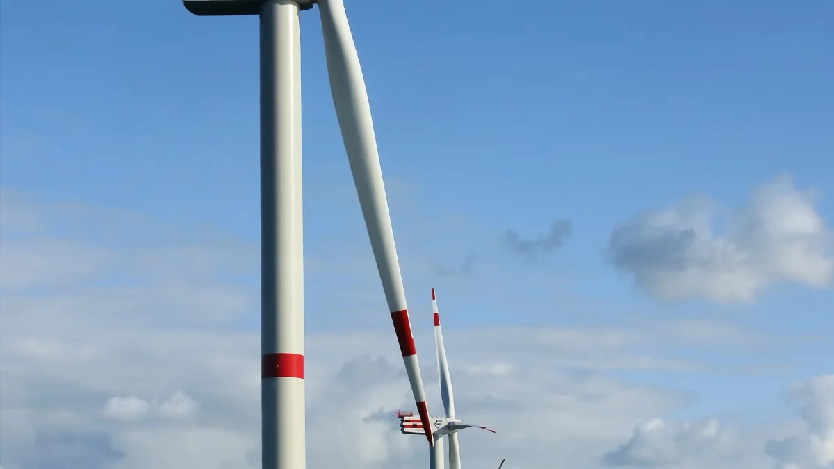
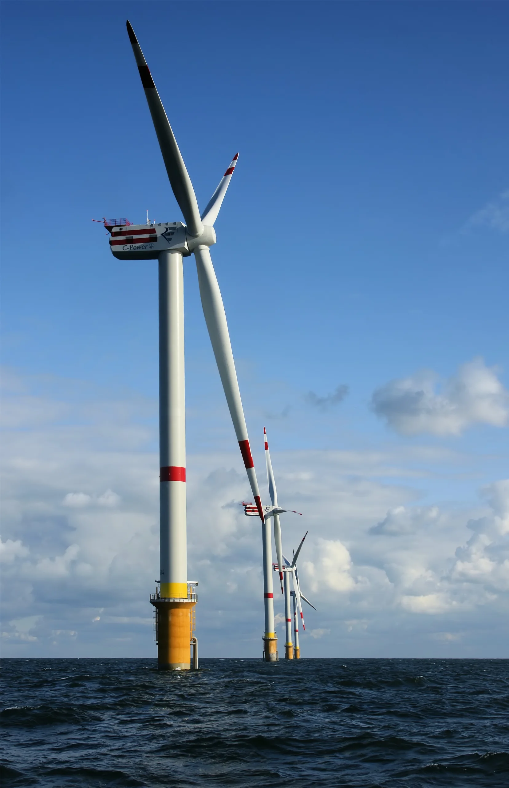
Drive past almost any modern wind farm on land or offshore and the rotors look identical. Almost every utility-scale machine uses exactly three slender fiberglass or carbon-fiber blades, never two and rarely four [1, 2]. That convergence is not an aesthetic habit but the balance point between fluid dynamics, gyroscopic mechanics, and structural cost [1, 2, 3].
Adding extra blades captures only a small fraction more energy because every moving blade disturbs the air behind it [1, 3]. Dropping down to two blades cuts material weight, yet creates severe uneven forces whenever the turbine turns into shifting winds [1, 2].
Momentum theory, finite-blade vortex models, and structural mechanics explain why three blades dominate global wind engineering [1, 2, 3]. Understanding rotor lift and drag mirrors the hydrodynamic efficiency principles explored in our guide on how submarines glide through dense water.
- 0.40 to 0.50
- Real Turbine Efficiency Typical operational power coefficient on three-blade utility rotors [1]
Why This Matters: Clean Power Economics at Scale
Modern offshore wind turbines stretch well over 100 meters in blade length. Each blade endures millions of cyclic gravity, gust, and centrifugal loads over a twenty-to-twenty-five-year service life [1, 2].
Choosing the wrong blade count can ruin a wind project financially. Adding a fourth giant blade raises tower, hub, and transport costs dramatically while delivering barely two to three percent extra energy [1, 3].
Clean grid power powers everyday technologies ranging from home cooling systems to modern electric vehicles replacing petrol engines. Squeezing maximum reliable energy out of each rotor keeps electricity affordable and turbines mechanically stable [1, 2].
How the Study Was Done: Actuator Disks and Vortex Models
Wind engineering textbooks and aerodynamic papers model turbine rotors using two complementary mathematical frameworks [1, 2, 3]. First, one-dimensional momentum theory treats a spinning rotor as a porous actuator disk slowing incoming airflow [1].
In 1919, German physicist Albert Betz applied conservation of mass and momentum across that disk [1]. He calculated how much kinetic energy a rotor can extract before slow air blocks fresh wind from entering [1].
Real rotors have discrete blades rather than an infinite uniform disk, creating helical tip vortices in the wake [1, 3]. To capture finite-blade losses, Valery Okulov and Jens Nørkær Sørensen refined Betz momentum theory using Goldstein vortex functions and Prandtl tip-loss factors [3]. Combined with structural dynamics handbooks by Burton and Manwell, engineers predict exact power and bending loads for one, two, three, and four blades [1, 2, 3].
Betz’s Law: Why Turbines Never Capture All Wind Energy
A common misconception assumes an ideal wind turbine slows passing air completely to zero speed. In reality, stopping air entirely inside a rotor swept disk would create an aerodynamic brick wall [1]. Fresh upwind air would simply flow around the stalled blades instead of passing through them [1].
Conversely, letting air rush through at full upstream speed extracts zero kinetic energy [1]. By solving the momentum balance, Betz proved maximum energy extraction happens when downstream wake speed falls to exactly one-third of upstream wind speed [1].
At that optimal slowdown ratio, the theoretical ceiling power coefficient equals 16/27, or roughly 59.3 percent [1]. Real utility-scale three-bladed turbines capture roughly 75 to 80 percent of the Betz theoretical limit, delivering practical coefficients between 0.40 and 0.50 [1].
Three unavoidable aerodynamic penalties explain why real rotors sit below the 59.3 percent ideal disk [1, 3]. First, spinning blades impart swirling rotation to the wake behind the rotor. That rotational kinetic energy leaves the turbine without turning the generator [1, 3]. Second, high-pressure air curls around blade tips toward the suction face, creating tip-loss vortices documented by Ludwig Prandtl and refined by Okulov and Sørensen [3]. Third, surface skin friction on fiberglass shells creates small profile drag losses [1].
Aerodynamic Lift and Why Two Blades Spin Faster
Modern utility turbines are lift machines, not flat-paddle drag windmills [1, 2]. As airflow crosses each twisted airfoil blade, pressure drops over the curved suction side and pushes on the pressure side [1]. That net aerodynamic lift force generates rotational torque around the central shaft [1, 2].
Crucial to blade count is the tip-speed ratio, which compares blade tip speed against oncoming wind speed [1, 2]. When a blade passes through a given column of air, it leaves a swirling turbulent wake behind it [1, 3].
How Three Blades Capture Energy Without Blocking Air
- Step 1
Airfoil Generates Aerodynamic Lift
Incoming wind bends over cambered blades, producing forward lift torque rather than wasteful flat drag [1].
If blades pass too slowly, clean wind slips untouched between the gaps. If too many blades crowd the swept circle, each blade cuts straight into the turbulent wake shed by the blade ahead of it [1, 3].
A two-bladed rotor can match much of a three-bladed turbine’s aerodynamic efficiency, yet only by spinning noticeably faster [1, 2]. Higher tip speeds create sharper aerodynamic whoosh noise and accelerate leading-edge rain erosion on composite blades [2]. Because aerodynamic noise scales steeply with tip velocity, residential planning rules strongly favor slower, quieter three-bladed rotors [1, 2].
Going the opposite route with four or five blades lowers optimal tip speed without boosting energy capture meaningfully [1, 3]. Once three blades sweep the wind column fast enough to engage oncoming air packets, adding more blades mostly adds weight, wake crowding, and tower cost [1, 3].
Gyroscopic Balance: Why Two Blades Shake the Tower
Mechanical dynamics explain why three blades defeated two-blade prototypes cleanly [1, 2]. Imagine a spinning two-bladed propeller aligned vertically for an instant, then horizontally a quarter-turn later [2].
Around the vertical yaw axis, a two-bladed rotor changes its mass moment of inertia dramatically twice every full revolution [2]. When changing wind direction forces the nacelle to swivel, those fluctuating inertial forces hammer the tower and hub [2]. Engineers call this cyclic hammering a two-per-revolution gyroscopic load [2].
Wait until you add a third blade spaced equally at 120 degrees. Mathematically, any symmetric rotor with three or more evenly spaced blades possesses a constant polar moment of inertia around its yaw axis regardless of rotation angle [1, 2].
When a three-bladed turbine turns to face shifting winds, gyroscopic resistance feels steady rather than pulsing violently twice per spin [2]. Two-bladed turbines tried using hinged teetering hubs to absorb those shocks, yet added mechanical complexity and maintenance cost [1, 2].
Three-bladed turbines also avoid abrupt vertical wind shear shocks. In a two-bladed machine, one blade hits peak upper-air wind speed at the exact moment its twin crosses in front of the steel tower [1, 2]. That tower casts a low-wind aerodynamic shadow at the bottom of the arc. With three blades staggered 120 degrees apart, torque pulses smooth out considerably [1, 2].
Pitch motors inside each blade root rotate blades slightly every second during gusty weather. Individual pitch control trims uneven wind-shear bending across the upper and lower sweep without shaking the main gearbox shaft [1, 2]. When hurricane gusts exceed design limits, pitch actuators turn all three blades edgewise into the wind, stopping rotation safely [1, 2].
Table 1 compares aerodynamic, structural, and acoustic behavior across one-, two-, three-, and multi-bladed rotor architectures based on wind engineering models [1, 2, 3].
| Rotor Configuration | Optimal Tip Speed Ratio | Gyroscopic Yaw Stability | Engineering Verdict |
|---|---|---|---|
| Single Blade + Counterweight | Very high (10+) | Severe imbalance and extreme tip noise | Experimental only; unacceptable acoustic noise [1] |
| Two Blades | High (8 to 10) | Strong cyclic 2p wobble when yawing | Cheaper blades, but noisy and needs teeter hub [1, 2] |
| Three Blades | Moderate (6 to 8) | Smooth constant yaw inertia around hub | Global standard: best cost, noise, and power ratio [1, 2, 3] |
| Four or More Blades | Low (2 to 5) | Smooth, heavy rotor inertia | Minimal extra energy for steep extra hub weight [1, 3] |
Compiled from Manwell et al. (2009), Burton et al. (2011), and Okulov & Sorensen (2008).
Why Old Farm Windmills Used Twenty Blades
If three blades work best for electricity, why do classic water-pumping ranch windmills carry twelve to twenty sheet-metal blades [1]? The answer comes down to starting torque versus high-speed power [1, 2].
A mechanical water piston needs strong initial twist just to start moving in gentle morning breezes [1]. High blade solidity catches low wind speeds directly and pulls hard at low RPM [1, 2]. However, once winds rise, closely packed blades choke incoming air and hit low maximum power efficiency [1, 3].
Electrical generators work in the opposite regime. They convert mechanical torque most compactly when shafts rotate cleanly at steady, faster speeds [1, 2]. Moving fluids efficiently inside thermal and energy machines shares tight engineering parallels with vapor-compression cooling cycles inside air conditioners.
What the study cannot tell us: Future Giant Rotors
Engineering consensus around three blades holds firmly for current land and fixed-bottom offshore turbines [1, 2]. Yet theoretical models cannot rule out niche changes as rotor diameters push past 250 meters at deep-sea sites [2, 3].
At extreme offshore scales where acoustic noise bothers nobody far out at sea, researchers periodically re-examine two-bladed downwind rotors to trim crane installation weight [2]. Even then, finite-blade tip losses and blade-root fatigue still challenge two-blade designs compared with three-blade units [1, 3].
Wind energy physics also depends on site turbulence, icing, and wake interference between neighboring machines inside dense wind farms [1, 2]. Rotor geometry alone never guarantees peak output without smart pitch control and wake steering across an entire array [1, 2].
Frequently Asked Questions About Wind Turbine Blades
Frequently Asked Questions
Why don't wind turbines have four or six blades to catch more wind?
Once three fast-moving airfoil blades sweep a circular area, they already interact with most incoming air. Adding a fourth blade only increases aerodynamic capture by a few percent while raising blade, hub, and tower costs steeply.
Can any wind turbine break the 59.3 percent Betz efficiency limit?
No. The Betz limit comes from fundamental conservation of mass and momentum in open air. Slowing air further than one-third upstream velocity forces incoming wind to spill around the rotor instead of passing through.
Why do wind turbine blades look twisted from root to tip?
The blade tip travels much faster through air than the section near the hub. Twisting the airfoil keeps an efficient angle of attack along the entire blade radius.
Why are farm water-pumping windmills built with many blades?
Multi-blade windmills have high solidity, generating strong low-speed starting torque to lift heavy water pistons in light breezes, even though their overall energy efficiency is lower.
Technical Terms and Definitions
Scientific terms used in this article
- Betz LimitMaximum Open-Wind Capture Limit
- The theoretical physical ceiling showing an open-flow rotor cannot convert more than 59.3 percent of wind kinetic energy.
- Tip-Speed RatioBlade Tip to Wind Speed Ratio
- The speed of the outermost blade tip divided by undisturbed incoming wind speed.
- SolidityBlade Area Ratio
- Total surface area of turbine blades divided by the circular area swept by the spinning rotor.
- Gyroscopic PrecessionSpinning Axis Resistance
- Inertial forces triggered when a rapidly spinning rotor turns to face a new wind direction.
- Tip VorticesSwirling Blade-End Eddies
- Trailing air spirals shed at blade tips where high-pressure air curls around to the low-pressure side.
Scientific References and Primary Literature
Wind Energy Explained: Theory, Design and Application (2nd ed.)
- Journal
- John Wiley & Sons
- Study Type
- Report
- Year
- 2009
DOI10.1002/9781119994367
Timeline
- 1919
Betz Momentum Limit Derived
Albert Betz proved an ideal actuator disk can extract at most 16/27 (59.3%) of wind kinetic energy.
- 2008
Finite-Blade Tip Losses Refined
Okulov & Sorensen quantified power penalties from trailing vortices on finite rotors.
- 2011
Three-Blade HAWT Standard Codified
Modern utility turbine handbooks balanced yaw inertia, tip noise, and structural load at three blades.
References
- ↩ Manwell, J. F., McGowan, J. G., & Rogers, A. L. (2009). Wind Energy Explained: Theory, Design and Application (2nd ed.). John Wiley & Sons.
- ↩ Burton, T., Jenkins, N., Sharpe, D., & Bossanyi, E. (2011). Wind Energy Handbook (2nd ed.). John Wiley & Sons.
- ↩ Okulov, V. L., & Sorensen, J. N. (2008). Refined Betz limit for rotors with a finite number of blades. Wind Energy 11(4), 415-426.


No comments yet. Be the first to join the conversation.