


Key Findings
- Airliners fly curved polar arcs because great-circle routes represent the shortest distance between cities on a spherical Earth [1, 3].
- Flight management computers fuse GPS timing, self-contained ring-laser gyroscopes, and ground VOR/DME radio beacons continuously [1, 2].
- Precision Instrument Landing System (ILS) antennas project horizontal centerline guidance and a 3-degree vertical glideslope down to concrete runways [3].
Open any flight tracker map and long-haul jets appear to fly puzzling detours over Greenland or Alaska rather than straight east-west across a wall chart. Those looping arcs are actually the shortest path across a spherical planet: great-circle routes [1, 3].
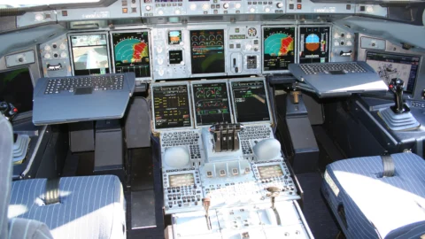
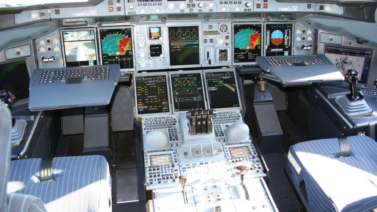
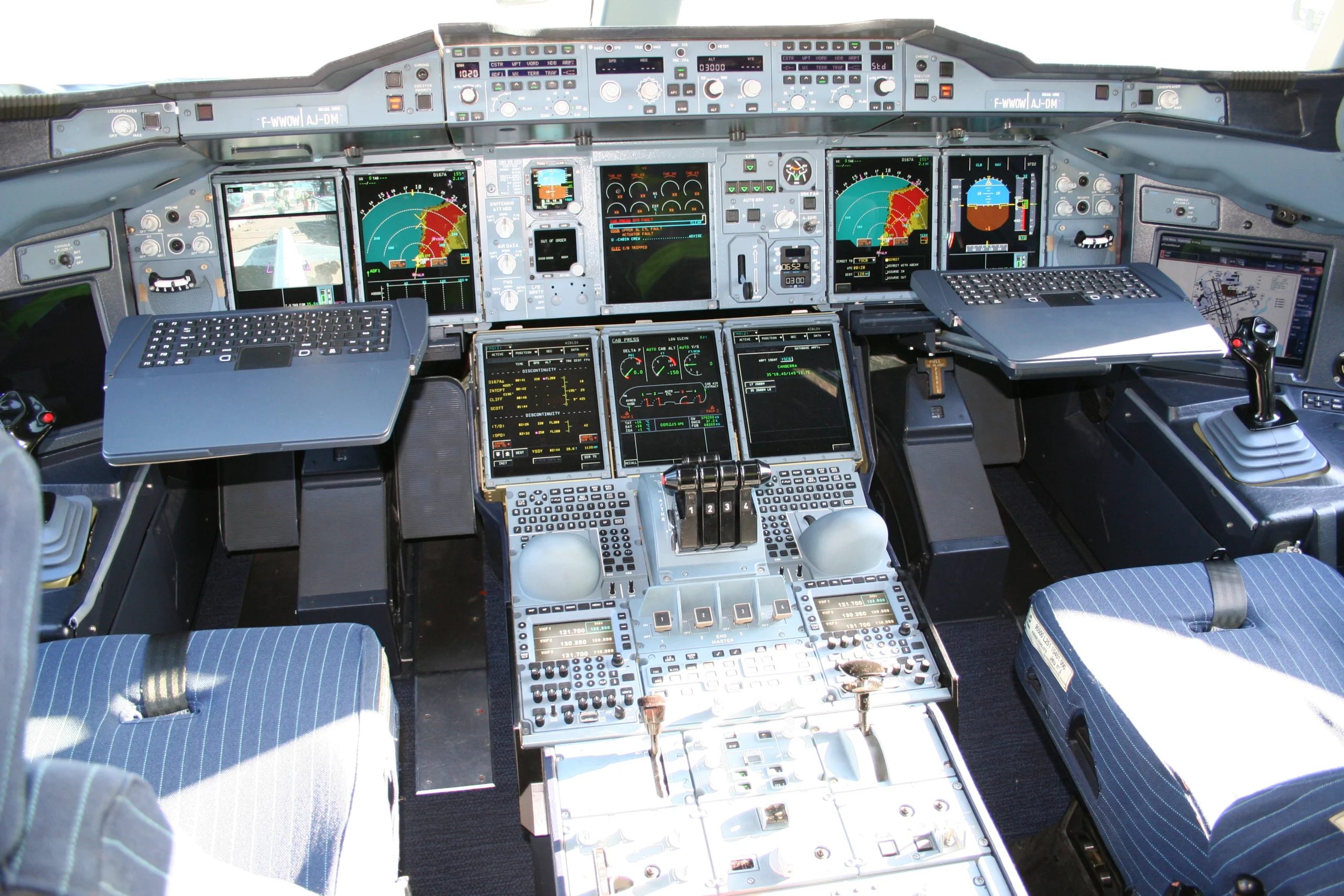
High above oceans and storm clouds, airliners never steer by looking out the windshield. Instead, pilots and flight management computers fuse satellite constellations, ring-laser gyroscopes, ground radio beacons, and precision landing beams [1, 2, 3].
Avionics handbooks and official FAA instrument manuals explain how multi-layered navigation systems guide aircraft down onto foggy runways on a 3-degree glide slope within meters of center [1, 2, 3]. Navigating featureless skies relies on the same three-dimensional inertial physics explored in our guide on how deep-sea submarines navigate underwater without GPS.
Why This Matters: Redundancy Across Empty Oceans
Cruising airliners cover roughly 850 to 900 kilometers every hour through shifting high-altitude jet streams [1, 2]. Over central oceans far outside radar range or inside blinding fog layers, visual landmarks vanish completely [1, 3].
Every kilogram of extra fuel burned flying sloppy zigzags raises ticket prices and carbon emissions. Yet safety always outranks fuel savings: losing a single GPS satellite signal must never leave pilots guessing where mountains lie [1, 2]. Commercial aviation therefore designs every primary flight path with multiple dissimilar navigation layers ready to cross-check or substitute for one another instantly [1, 2].
Modern aircraft engineering solves both challenges by blending independent mathematical physics sensors inside redundant avionics buses [1, 2]. Precision timing electronics resemble high-speed signal processing systems discussed in our analysis of optical laser physics and computerized transport control systems.
How the Study Was Done: Avionics Handbooks and FAA Rules
Modern air navigation architecture rests on decades of civil aviation engineering and formal international certification standards [1, 2, 3].
In Avionics Navigation Systems, Myron Kayton and Walter Fried formalized the equations coupling inertial acceleration integration, radio bearing triangulation, and Doppler velocity sensing [1]. Carry-forward digital architectures in Cary Spitzer’s Digital Avionics Handbook further detail modular flight management computers, ARINC data buses, and cockpit display integration [2].
On the operational cockpit side, the Federal Aviation Administration’s Instrument Flying Handbook translates sensor theory into exact airway structures, RNAV waypoint tolerances, and 3-degree Instrument Landing System approach criteria [3]. Together, engineering theory and regulatory handbooks govern nearly every commercial jetliner skyward today [1, 2, 3].
Why Curved Map Lines Are Actually Shortest: Great Circles
Flat classroom wall maps distort spherical distances severely, especially closer to polar latitudes [1]. Stretching Greenland wide enough to sit flat makes east-west straight lines look deceptively direct on Mercator projections [1].
On a real three-dimensional Earth sphere, the shortest surface route between two cities follows a great circle [1, 3]. Mathematically, a great circle marks where a flat plane slicing straight through Earth’s center meets the surface [1]. Because northern latitude circles shrink rapidly toward the pole, curving northward between London and Seattle cuts hundreds of kilometers off total flight distance [1, 3].
Air traffic planners still modify pure great-circle lines slightly to ride fast upper-tropospheric jet streams [1]. Heading east across the Atlantic with a 150-knot tailwind saves far more fuel than fighting headwinds along a strict geometric arc [1]. Daily North Atlantic Tracks shift slightly north or south each morning to balance great-circle geometry against changing atmospheric winds [1, 3].
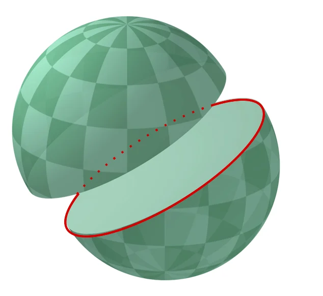
Area Navigation (RNAV) empowers jets to trace those direct great-circle coordinates from waypoint to waypoint rather than zigzagging from one ground radio tower to another [3].
Radio Beacons, Inertial Lasers, and Satellite Blending
Rather than trusting one sensor blindly, the Flight Management System cross-checks three distinct physical worlds simultaneously [1, 2]. First, satellite navigation receivers decode atomic-clock timing radio waves from multiple orbiting satellites to fix global latitude, longitude, and altitude [1, 2].
Second, the Inertial Reference System uses three orthogonal ring-laser gyroscopes and accelerometers spinning light beams inside tiny quartz cavities [1, 2]. By tracking optical interference shifts without any outside antenna, inertial computers detect subtle turns, climbs, and drift rates entirely self-contained [1, 2]. Because inertial systems need zero external signals, neither jamming nor solar storms can immediately blind aircraft attitude displays [1].
How Flight Computers Cross-Check Every Turn in Midair
Third, terrestrial VHF Omnidirectional Range (VOR) ground beacons broadcast phase-shifted radio waves across 360 magnetic radials, often paired with Distance Measuring Equipment (DME) slant-range pulses [1, 3]. Even if satellite links flicker, DME radio triangulation over continents snaps position estimates right back onto airway tolerances [1, 3].
How Jets Land in Zero Visibility: The 3-Degree ILS Beam
En-route accuracy within one kilometer works comfortably at 11,000 meters cruise altitude [3]. Touching down safely requires alignment within meters of concrete runway centerline [3]. When thick fog blankets an airport down to runway lighting limits, pilots engage the Instrument Landing System (ILS) [1, 3].
Aviation rules grade ILS installations into progressive visibility categories depending on runway precision [3]. Under standard Category I approaches, pilots must see runway lights by 60 meters above touchdown [3]. Advanced Category III autoland-capable airfields synchronize dual antennas and redundant cockpit autopilots so widebody jets touch centerline gently even when forward fog limits visibility below 100 meters [2, 3].
Two ground radio antennas placed beside the runway work in tandem [3]. First, the localizer sits beyond the departure end, projecting overlapping radio lobes straddling the exact runway centerline [1, 3]. Left-of-center flies into a 90-Hz modulated tone while right-of-center enters a 150-Hz lobe, centering cockpit crosshair needles when signal strengths match evenly [1, 3].
Second, a glideslope transmitter beside the touchdown zone projects a vertical radio plane tilted upward at roughly 3 degrees [3]. Following both crosshairs keeps a jet descending steadily toward painted touchdown markers at safe sink rates [1, 3]. Even when dense cloud hides the tarmac until seconds before wheel contact, crews track that 3-degree beam smoothly [1, 3].
Table 1 contrasts primary aviation navigation technologies across physical working principles, accuracy envelopes, and cockpit roles [1, 2, 3].
| Navigation System | Core Physical Principle | Operational Domain | Primary Aviation Advantage |
|---|---|---|---|
| GNSS / GPS Satellites [1, 2] | Microwave time-of-flight ranging | Global oceanic and continental | Meter-level 3D position anywhere without ground stations |
| Inertial Reference (IRS) [1, 2] | Ring-laser gyroscopes & accelerometers | Self-contained anywhere | Unjammable attitude, heading, and backup tracking |
| VOR / DME Beacons [1, 3] | VHF phase radials & pulse slant range | Continental airways | Independent ground backup cross-check for RNAV drift |
| ILS Localizer & Glideslope [1, 3] | Dual-lobe VHF/UHF radio beams | Final 10 to 15 km runway approach | Guides Category I to III landings down 3-degree glide path |
Compiled from Kayton & Fried (1997), Spitzer et al. (2014), and FAA Instrument Flying Handbook [1, 2, 3].
How Autopilot Computers and Pilots Share Cockpit Duty
Digital flight management computers handle continuous wind correction, great-circle turn banking, and vertical fuel-saving descents smoothly [2]. Pilots load verified departure, airway, and approach procedures before engine start, cross-checking every programmed waypoint against aeronautical charts [2, 3].
Notice that autopilot never flies unsupervised [2, 3]. Air traffic controllers separate jets vertically and horizontally along airway corridors via transponder squawk beacons and ADS-B automatic position broadcasts [2]. Pilots verify heading, vertical speed, and altitude constraints continuously. Crews also stand ready to take manual stick control instantly during crosswind gusts or go-arounds [2, 3].
Before every oceanic crossing, flight dispatchers and cockpit crews verify Minimum Navigation Performance Specifications [1, 2]. They confirm dual inertial alignment and satellite integrity ahead of leaving coastal radar coverage [1, 2]. Every cleared oceanic waypoint undergoes independent cross-checking by both captain and first officer so no single typing mistake shifts an aircraft onto an adjacent parallel track [2, 3].
Environmental efficiency shares physics parallels with terrestrial thermal and aerodynamic machines explored in our guide on precision fluid flow regulation in air conditioners.
What the study cannot tell us: Jamming and Magnetic Drift
Even redundant multi-sensor avionics face operational boundaries requiring careful pilot awareness [1, 2, 3]. High-altitude inertial gyroscopes slowly accumulate positional drift over long flights if left uncorrected by external GNSS or DME radio updates [1].
Regional conflict zones also increasingly experience intentional GPS radio jamming and spoofing, forcing flight crews back onto DME-DME ground triangulation and pure inertial dead reckoning [1, 2]. Earth’s magnetic poles also migrate steadily over decades [3]. Aviation authorities must periodically repaint runway compass numbers and recalibrate airport VOR stations so cockpit charts match magnetic north [3].
Notice that RNAV satellite approaches with vertical guidance (LPV and VNAV) now extend precision 3-degree glide paths to smaller regional airports without expensive steel localizer arrays [3]. Combining space-based augmentation signals with onboard inertial smoothing improves approach access dramatically across mountainous terrain and island airstrips [1, 3].
Extreme convective thunderstorm updrafts and volcanic ash clouds cannot be solved by radio navigation beams alone [2]. Weather radar inside the nose cone scans moisture reflectivity miles ahead so pilots steer dynamically around severe turbulence cells while staying safely inside assigned airspace corridors [2, 3].
Frequently Asked Questions About Aircraft Navigation
Frequently Asked Questions
Why do international flight maps look curved toward the North Pole?
Flat map projections stretch polar areas sideways. On our spherical Earth, the shortest geometric route between two distant cities is always a curved great-circle arc passing closer to higher latitudes.
Can modern airliners still navigate safely if GPS signals disappear?
Yes. Commercial jets combine self-contained ring-laser inertial reference units with ground-based DME distance radio stations and VOR beacons, seamlessly cross-checking position without satellites.
How do pilots land safely when thick fog hides the runway?
Crews follow ground-transmitted Instrument Landing System (ILS) radio beams projecting horizontal centerline guidance and a 3-degree vertical glideslope directly onto the runway threshold.
Why are runways numbered like 09 or 27 instead of names?
Runway numbers correspond to the nearest 10 degrees of magnetic compass heading. Heading east (090 degrees) is marked Runway 09, while approaching the same concrete strip westbound (270 degrees) is marked Runway 27.
Technical Terms and Definitions
Scientific terms used in this article
- Great-Circle RouteShortest Earth Sphere Path
- The shortest surface path connecting two points on a sphere, formed by slicing a plane through Earth’s center.
- VOR (VHF Omnidirectional Range)Ground Radio Radial Beacon
- A terrestrial aviation transmitter broadcasting 360 magnetic azimuth bearings in the 108 to 117.95 MHz band.
- ILS (Instrument Landing System)Precision Runway Approach Beams
- Dual localizer and glideslope radio transmitters guiding aircraft along runway centerline and a 3-degree descent angle.
- Inertial Reference SystemSelf-Contained Laser Gyro Tracking
- An onboard unit tracking position shifts solely via accelerometers and ring-laser gyroscopes without outside radio waves.
Scientific References and Primary Literature
Avionics Navigation Systems (2nd ed.)
- Journal
- John Wiley & Sons
- Study Type
- Report
- Year
- 1997
DOI10.1002/9780470172551
Timeline
- 1949
Omni-Range VOR Standardized
Civil aviation adopts VHF Omnidirectional Range radio radials worldwide.
- 1970s
Ring-Laser Inertial Navigation
Self-contained laser gyroscopes remove mechanical gimbal drift in jetliners.
- 1990s+
GPS/RNAV Area Navigation
Direct great-circle waypoint routing and precision 3-degree LPV approaches expand globally.


No comments yet. Be the first to join the conversation.